Week 19: Project Development

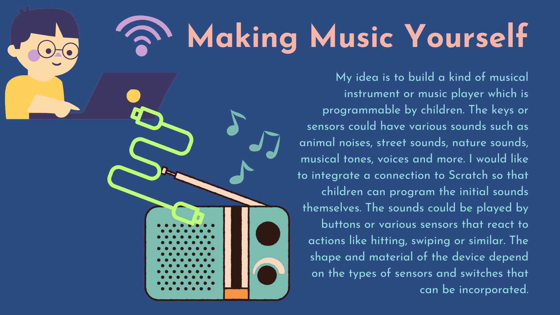
First Idea: Soundbox

Second Idea: Experimenting with Conductive Dough

Making Circuits

After working on some of the weekly assignments with my children to simply experiment more with how I can engage children with the topics, I thought about experimenting with my children for the final project as well. My idea was to work with conductive dough now.I would like to construct a kit of conductive dough to experiment with basic electronic concepts like circuits, conductivity, resistance, and simple devices like LEDs and buzzers. By inserting components into the conductive dough, children can see firsthand how electrical circuits work. For example, creating a simple circuit with a battery pack and an LED can teach about the flow of electricity, while adding dough switches can demonstrate open and closed circuits.

Programming Interaction

  • Touch Sensor: Using the conductive dough as touch-sensitive input for the microcontroller, children can create projects that respond to touch. This could involve playing sounds, changing light patterns, or even interacting with a computer.
  • Learning to Code: Maybe it will be possible to work on simple programming tasks (making an LED blink or controlling the pitch of a buzzer, make different sounds...).

Planning the First Steps

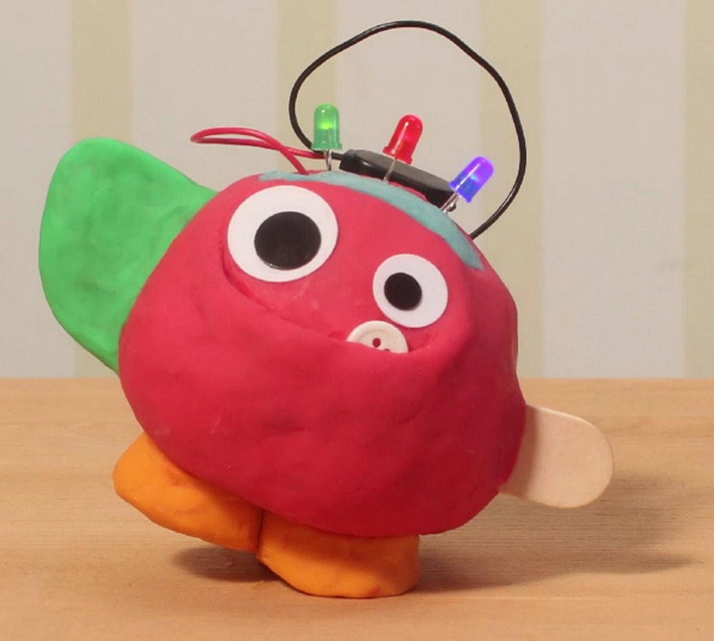
Since this is a project for children, I want to incorporate the ideas of children and develop the project together. Therefore, I asked my daughters (5 and 9 years old) if they would like to work with conductive dough and what ideas or wishes they have for it. Both were very excited about the idea and wished that the dough could light up and speak.

We have initially planned two afternoons of work. On one afternoon, we wanted to make the dough together, and on the other afternoon, build circuits with LED and perhaps also produce sounds.

Making the Conductive Dough

Online, there are some recipes for conductive and non-conductive dough. We used the following recipe:

Conductive Dough:

  • 1 cup water
  • 1/4 cup salt
  • 1 1/2 cups flour
  • 1 teaspoon vegetable oil
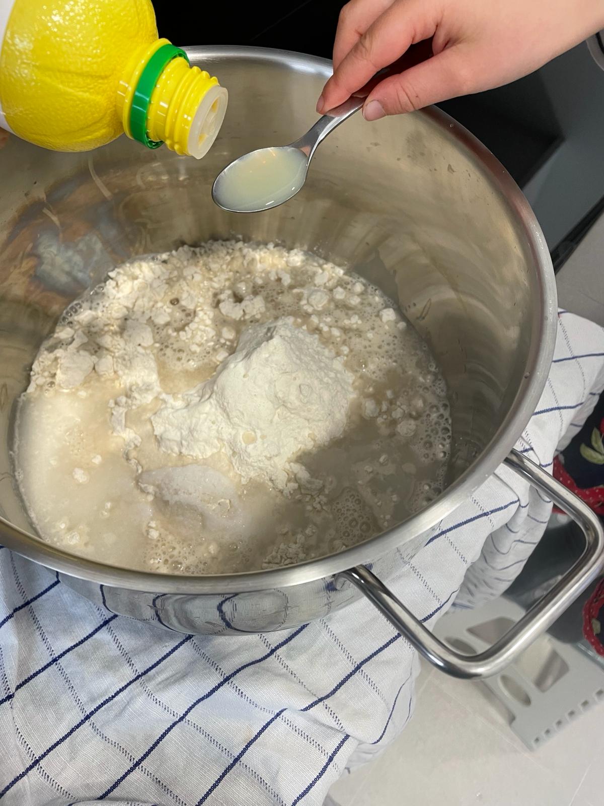
  • 1 teaspoon lemon juice Food
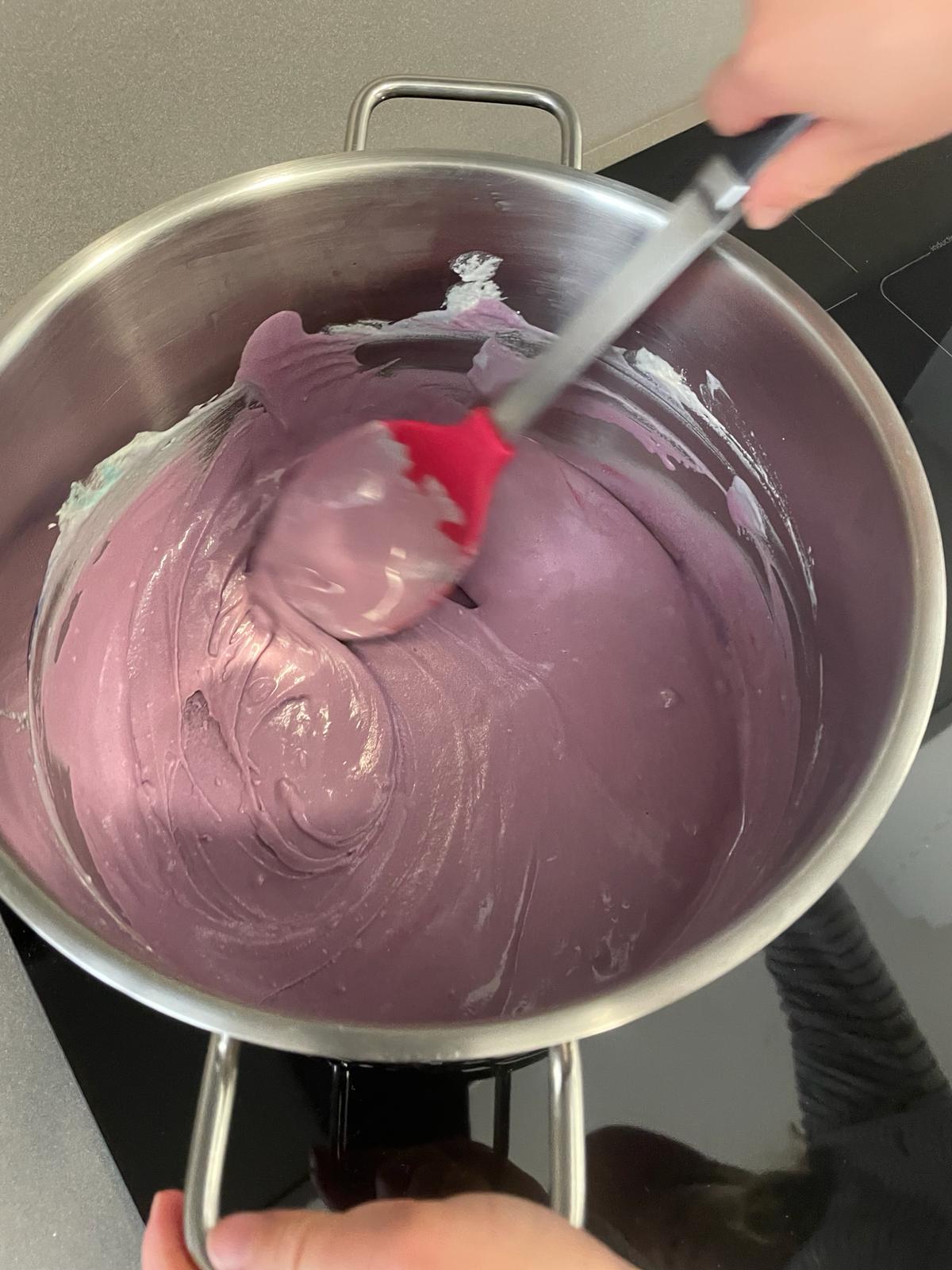
  • Food coloring

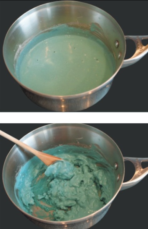
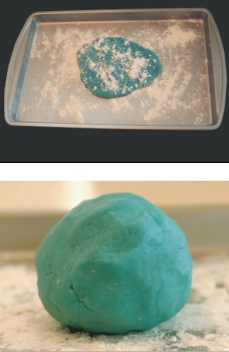
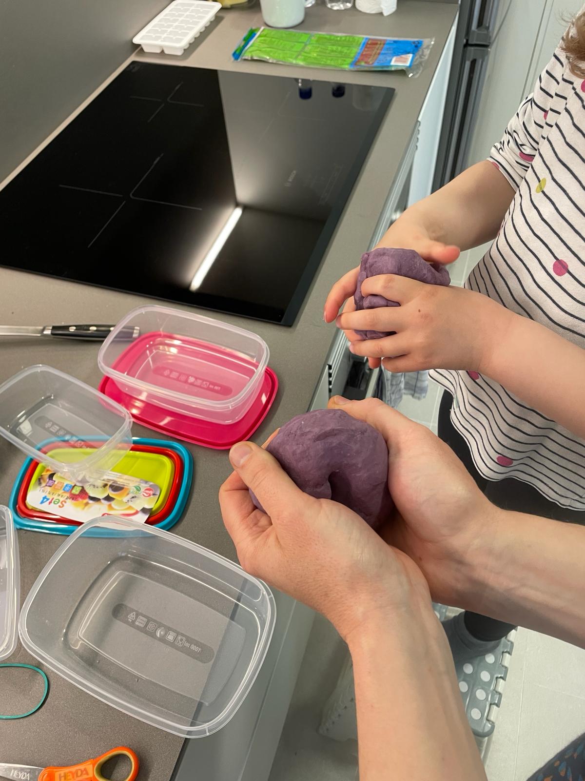
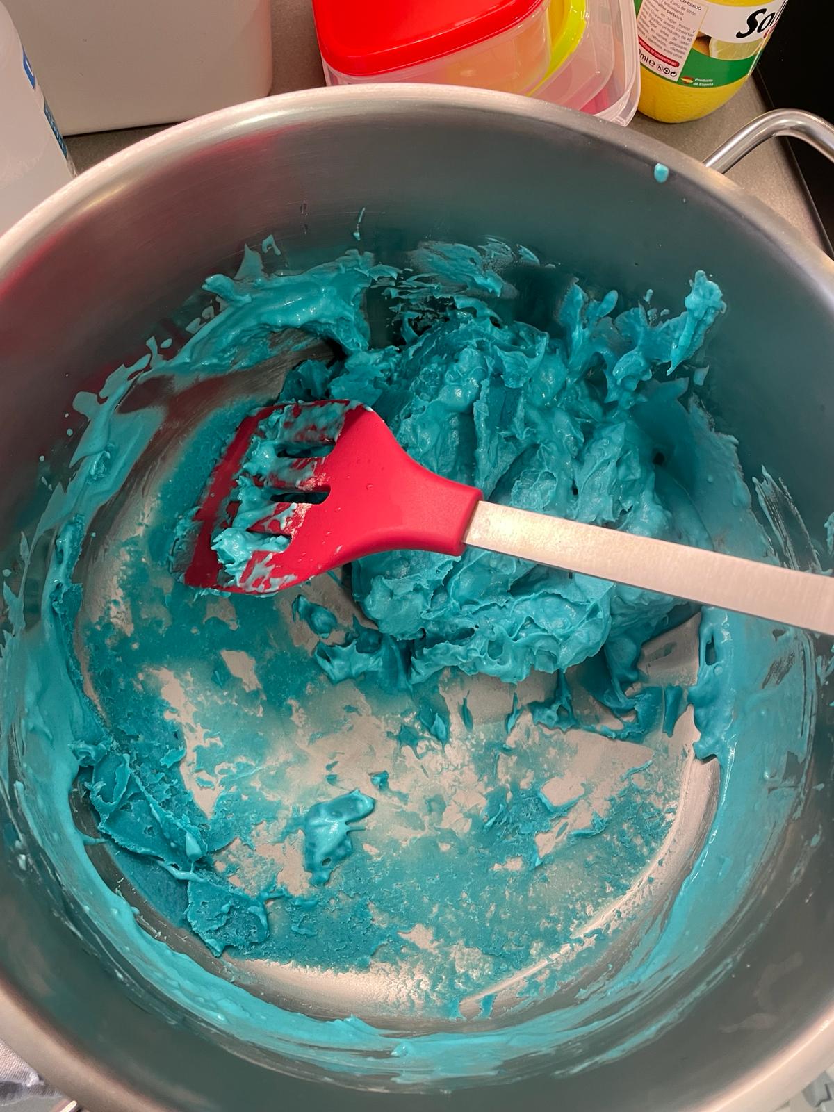
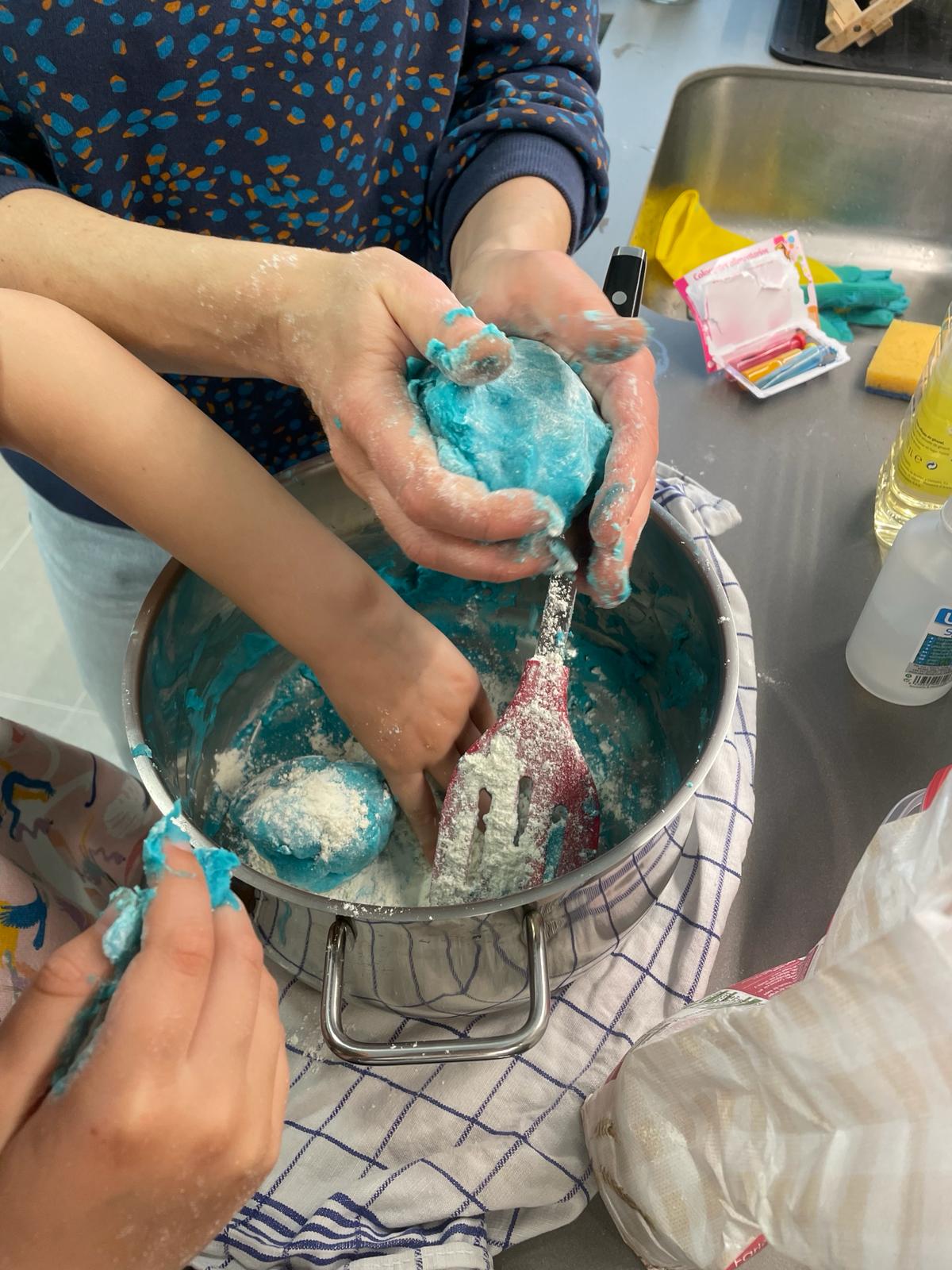
We had to mix the ingredients and then heat them until the mass begins to solidify. Then we kneaded it until a firm and not too sticky mass was formed.

Non-Conductive Dough:

  • 1/2 cups flour
  • 1/4 cup sugar
  • 1 1/2 teaspoons oil
  • Distilled water
  • Food coloring

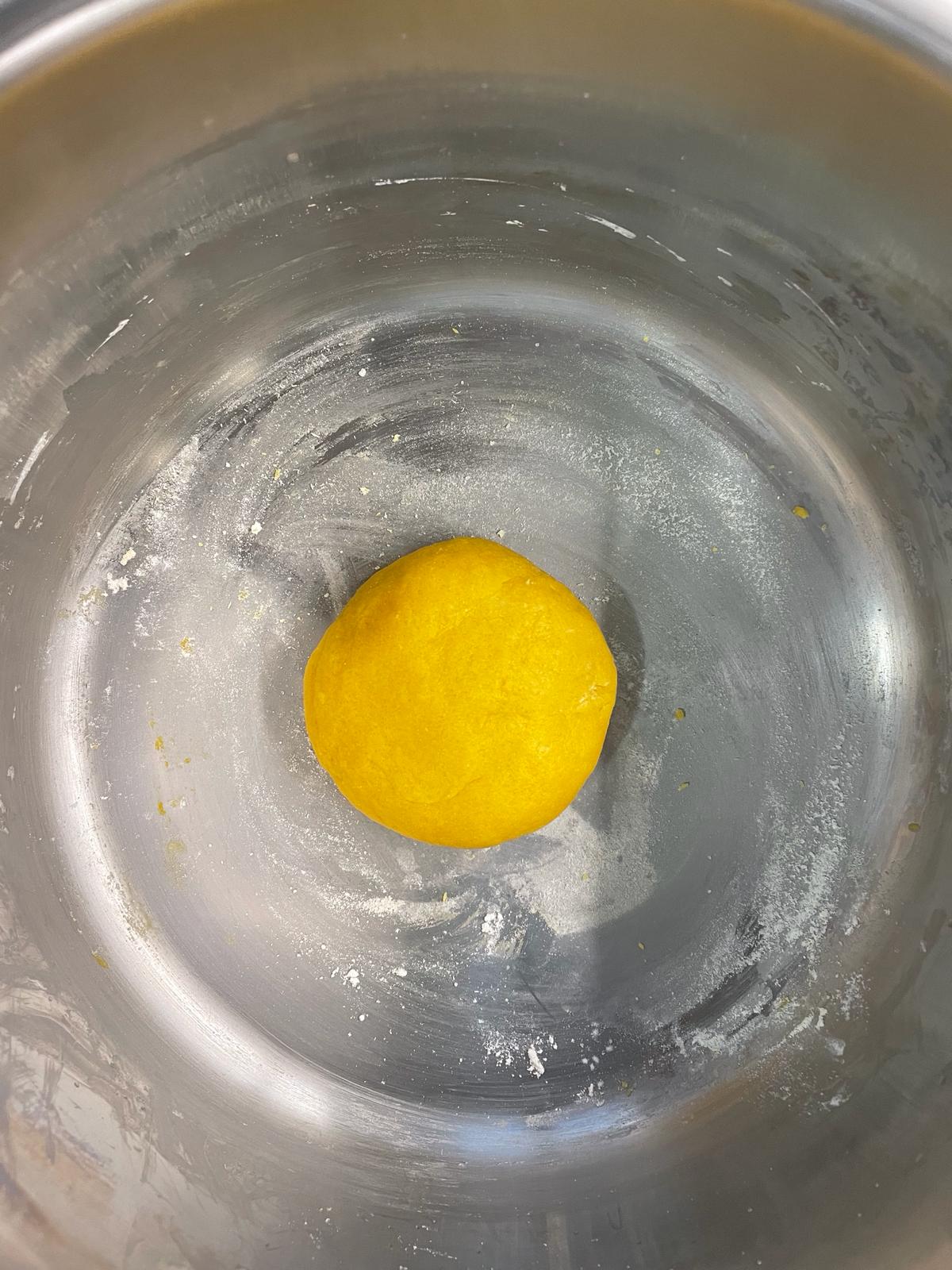
For the non-conductive mass, we combined flour, sugar, food coloring, and oil and then added distilled water until a good kneadable mass was formed.

We stored the dough in airtight containers. The dough seemed very good to us at first. But when we took it out two days later, we found that it had become extremely sticky and we could not process it as it was. We then kneaded in a large amount of additional flour. In hindsight, it turned out that we should have used more salt instead of flour because the conductivity of the dough was very limited. More on this in the next step.

First Experiments

Circuit

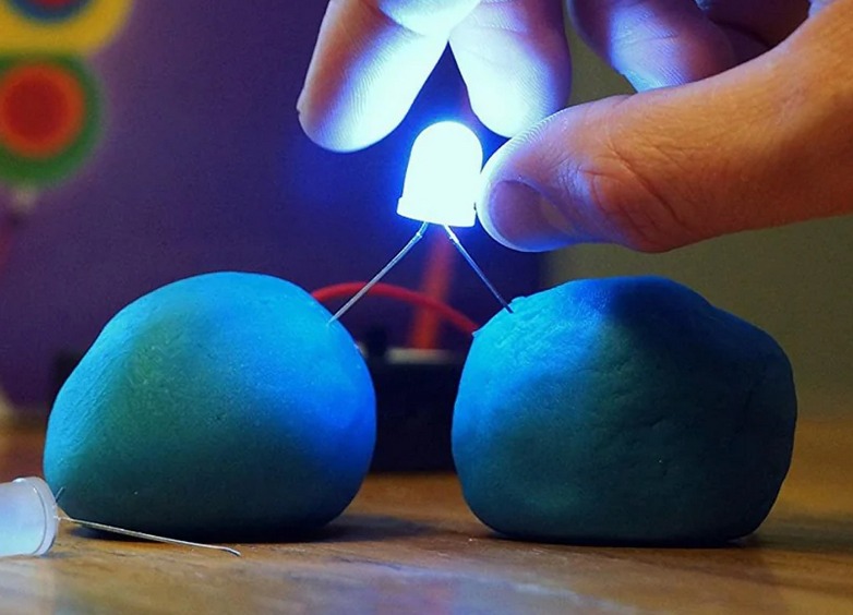
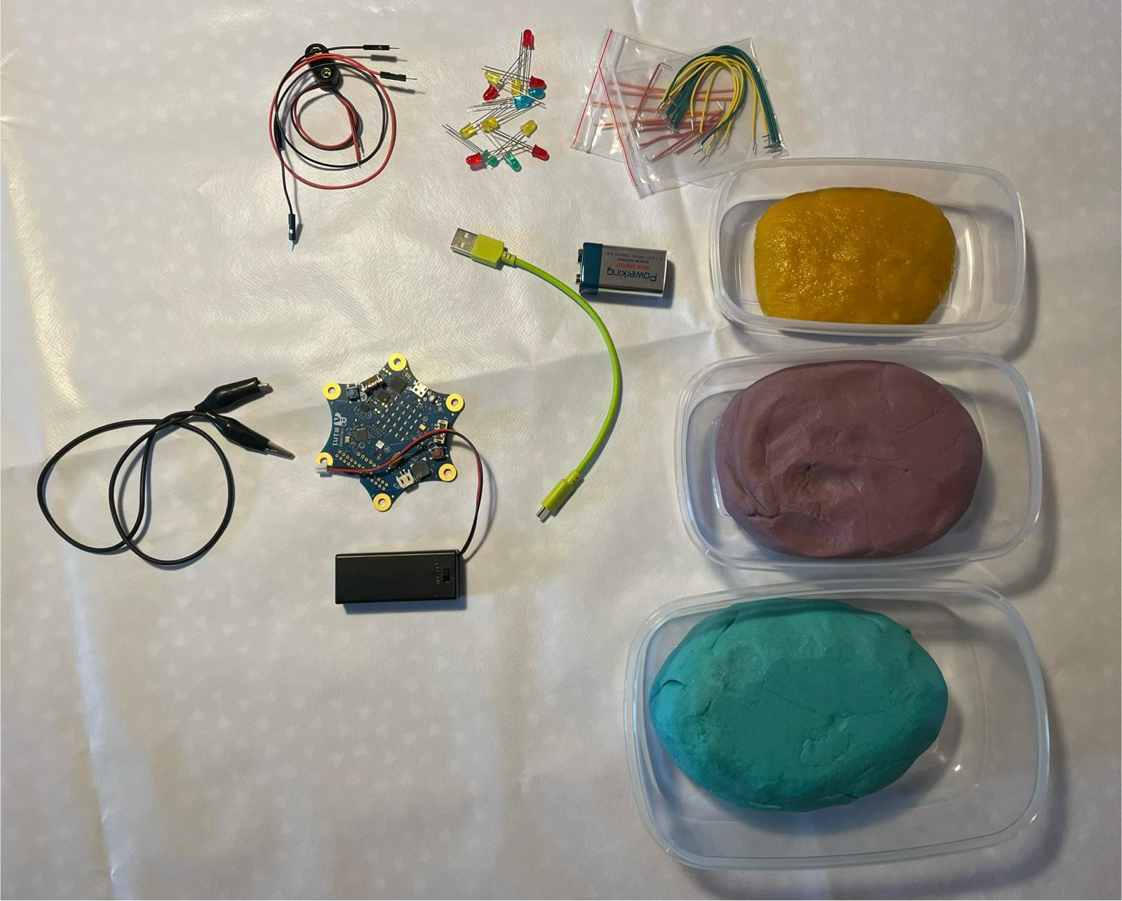
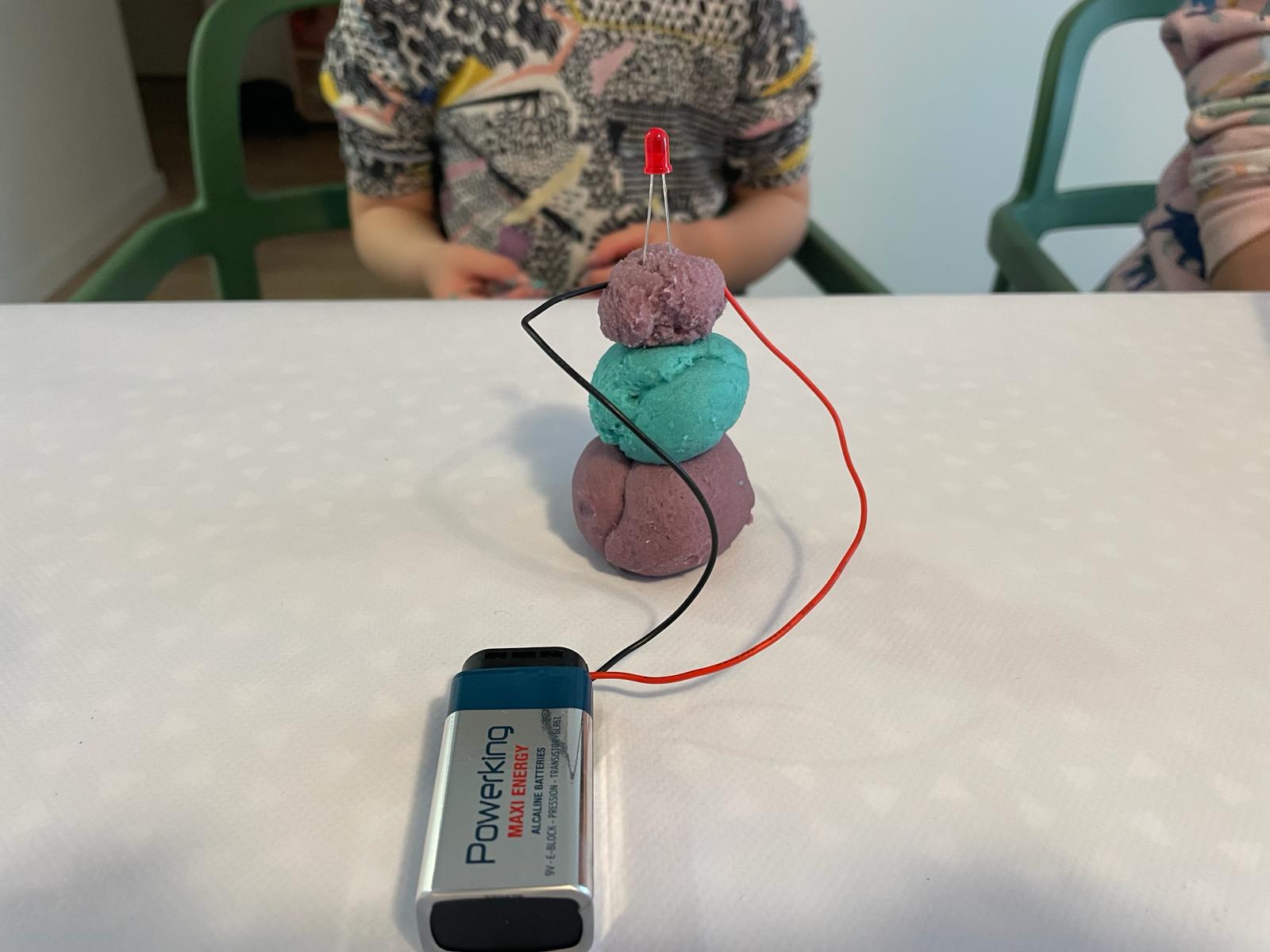
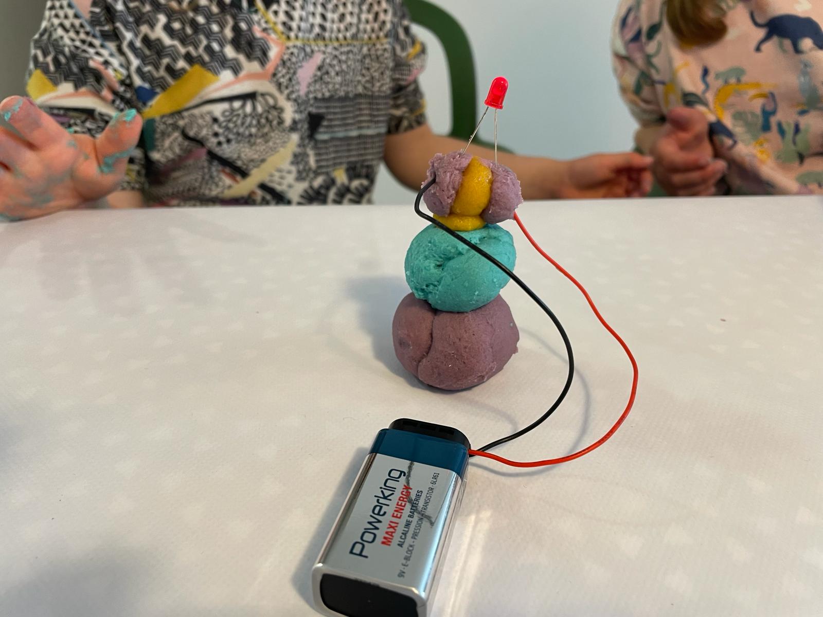
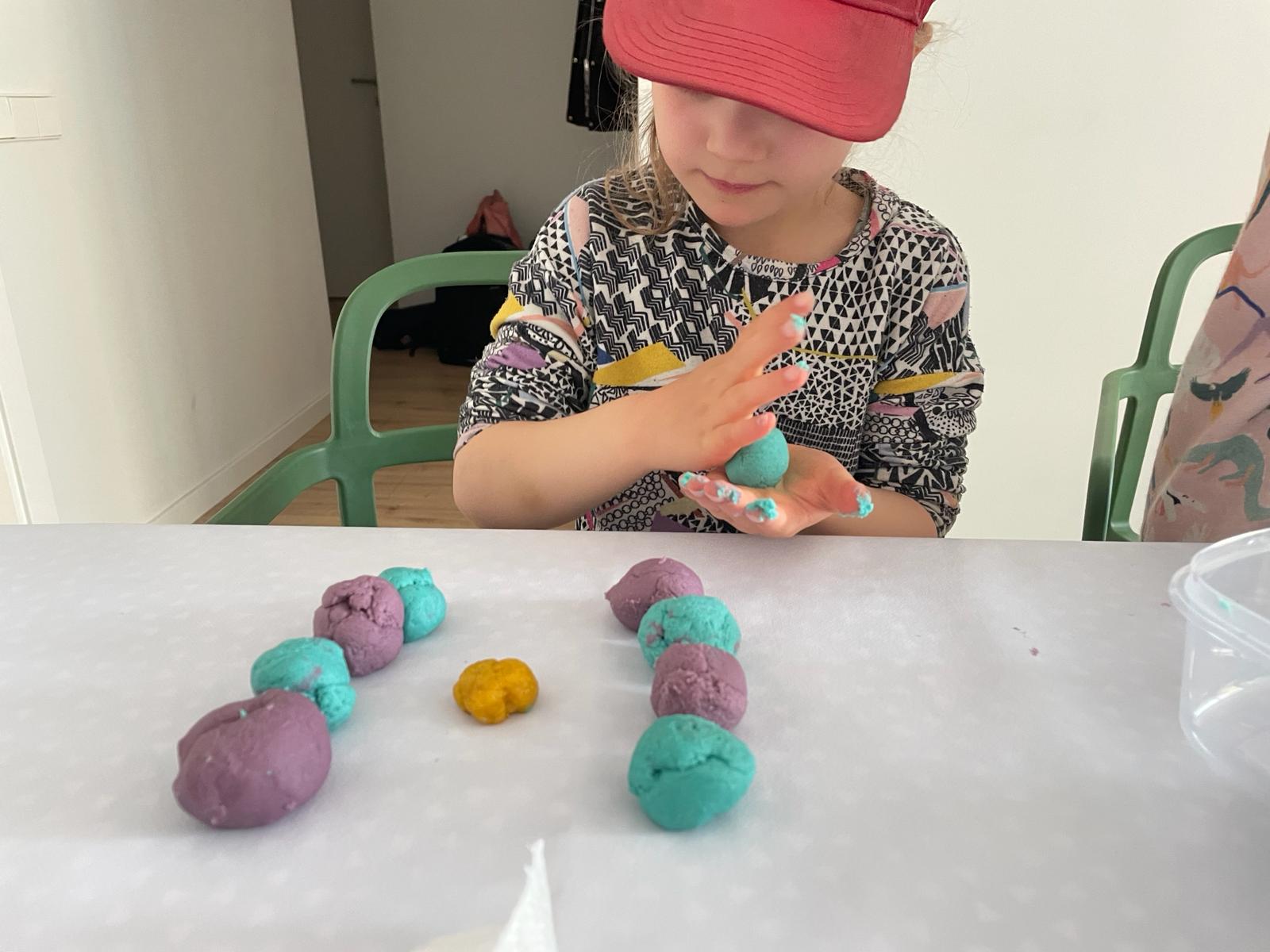
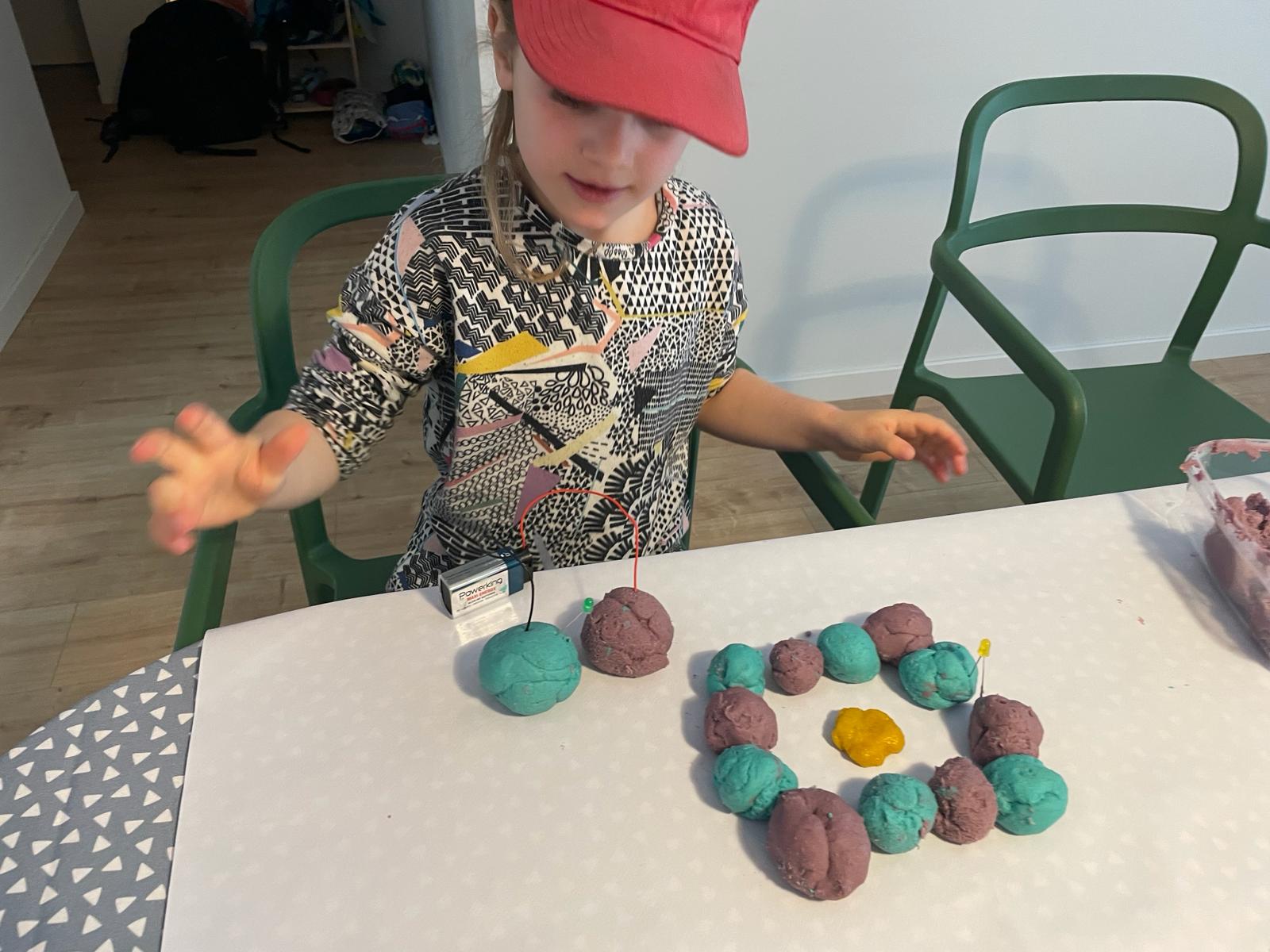
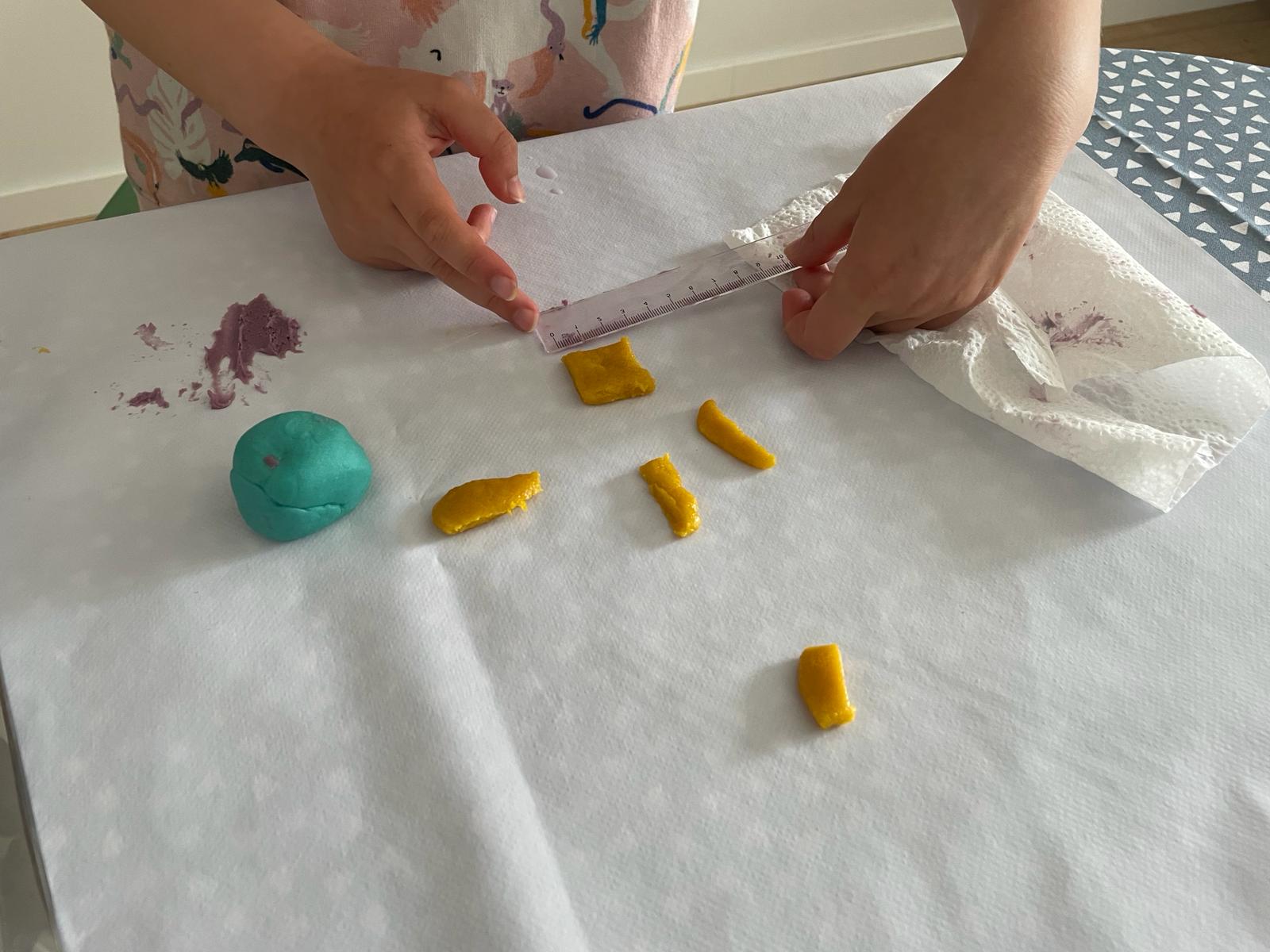
To introduce the two children to the theme, I spread all the necessary materials on the table. I then gave them a brief instruction and explained how circuits work and what they need to pay attention to in order to make an LED light up. Especially my younger daughter found it extremely boring and was totally impatient. I then just let her start working with the dough. I was fascinated by how quickly both children got into kneading and playing and very quickly found out what works and what doesn't. I also did not think that the attention span would be so large. When I suggested after the first test phase that we could now stop, both had some ideas and continued working for some time.

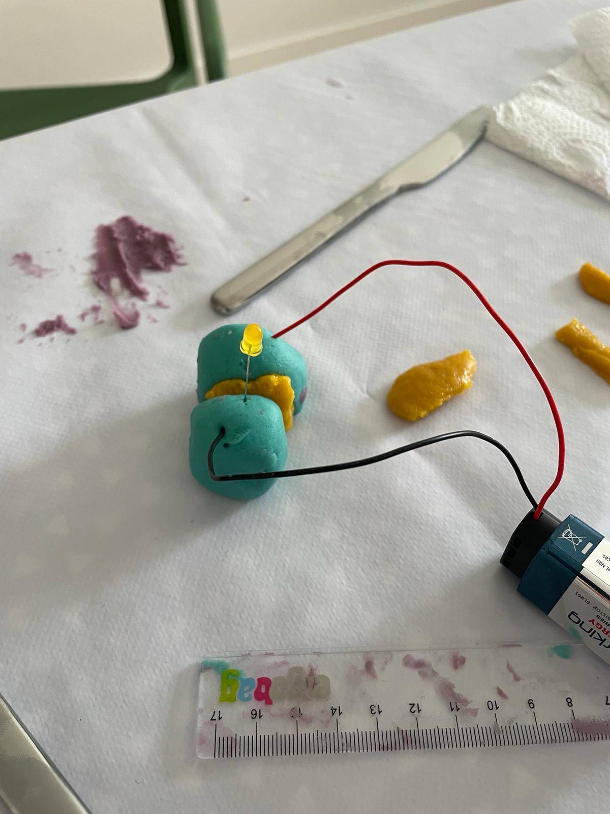
From creating the circuits in connection with battery, dough, and LED, I took away the following:

  • I was surprised by how long both children were attentive and tried out very independently and self-determined whether the LED could light up or not.
  • Explanations on my part did not interest them so much, but they quickly figured out what they needed to do to make the LED light up.
  • We found out that the current flow was unfortunately too weak to light up more than one LED. We suspect that this was because the conductive dough was not conductive enough.

Learnings:

The recipe for the dough should be changed so that the dough sticks less and conducts electricity better, to test whether multiple LEDs can light up simultaneously and whether we can also achieve other effects such as creating sounds or other applications.

Generating Sounds

To get closer to the wish that the dough could speak, we first dealt with generating sounds. I programmed two pins of the "Calliope" so that a tone is generated when the pin is connected to GND on one hand and the resistance between the two pins changes at the same time. I wanted to generate the change in resistance by pressing on the dough. Unfortunately, this did not work. Probably the values were too low, so pressing on the dough had no effect. At the same time, however, the children found out that by simply opening and then closing the circuit, two different tones could be generated. Experimenting with this effect was a lot of fun for them.

More Soundtests

To make some progress, we tested materials that can generate sound. We found that not every material can produce sound. Even when we rolled something over the capacitive sensor, we couldn't produce sound well. But when we touched the sensor, it worked well.

Project Development Schedule

February to April

  • Idea generation, experimentation, testing (see above)

May 1st to May 8th

  • Research of items I need to buy (Speaker, DFPlayer mini)
  • Decision on an additional element (LED) - finally there was not enough time
  • Conduct initial tests on the communication between boards
  • Research on recipes for gummy bears and test them

May 8th to May 15th

  • Further research on the communication between the boards
  • Test Arduino programming with Barduino and DFPlayer Mini
  • Start design of the Soundboard with ESP32-S3-Wroom-1
  • 3D scanning of animals

May 15th to May 22nd

  • Design the CNC wood box
  • Design the laser cut files
  • Design the files to make the animal molds
  • CNC the animal molds
  • Production of PCB, CNC, soldering
  • Search and download animal sounds
  • Prepare SD card with animal sounds

May 22nd to May 29th

  • Burn the molds to make them food-safe
  • Design the laser cut box and layers
  • Laser cut for wood box and packaging of the experiment kit
  • CNC the wood box
  • Assemble and paint the wood box
  • Vinyl cut for box design
  • Programming the PCB

May 29th to June 5th

  • Wiring the electronics in the box
  • Testing the electronics in the box
  • Applying the vinyl print
  • Assembling the box
  • Making gummy bears for the box
  • First video recordings for video and slide

June 5th to June 7th

  • Continue video recordings
  • Preparing video and slide

June 7th to June 15th

  • Documentation

Construction of the Sound Box

Creating craft kits

Sound Box & Experiment Kit

3D Scanning, Designing, Cutting

For the set, I wanted to create molds to make gummy bears. Together with my children, we selected small toy figures to create 3D scans. We chose an elephant, a dolphin, and a bear. It turned out that the bear was very difficult to scan. Its surface texture was too uneven. Therefore, I ultimately decided to download a model of the polar bear.

This is how I scanned the dolphin and the elephant. I already had the Scaniverse app installed on my phone. I placed the figures in an easily accessible area in the living room so I could walk around them. Then, I made several rounds around them, scanning the objects very thoroughly. I had to repeat the process several times to create a really good file.

MeshLab and Rhino

I then sent the file to myself as a mesh and opened it in Rhino. However, I quickly realized that the mesh files were very uneven, and I wasn't sure if I could achieve a good result this way. So, I looked for a program to easily edit meshes. I found and installed MeshLab. Since I hadn't worked with meshes before and this seemed very complicated at first glance, I used MeshLab's automatic optimization options.

Mesh simplification (optional):

  • Go to Filters > Remeshing, Simplification and Reconstruction > Quadric Edge Collapse Decimation. This reduces the number of polygons in your model, simplifying and potentially optimizing the file. Set the target value for the number of faces and click Apply.

Smoothing the surface (optional):

  • Go to Filters > Smoothing, Fairing and Deformation > Laplacian Smooth. This smooths the surface of your model. Choose the number of iterations and click Apply.

Both worked great.

I was then able to use the new files more effectively. In Week 12, Molding & Casting, I had already produced a mold. The process for creating the salamander, which I also use for the kit, can be found on Week 12 page.

Preparation in Modela

I took the animal files and replaced the figures. Then, I prepared the files in Modela. I used the same settings as in Week 12, Molding & Casting. After preparing the files, I uploaded them to the cloud and started the cut.

Milling

First, I had to prepare the machine to mill a wax block. For this, the machine's bed (which is always inside for PCB milling) had to be removed. The machine also needed to be cleaned, so I used a vacuum cleaner. Then, I inserted the drill and set the zero point. Although I set the zero point carefully, the milling went over the edge. Initially, I didn't understand why. It turned out that I hadn't set the zero point correctly when generating the file in Modela. So, I reopened the Modela file and adjusted the zero point. Then, I flipped the wax block and restarted the cut. Everything worked perfectly this time. The result was very impressive, as even the tiny elements of the elephant, bear, and dolphin were clearly visible.

Casting

To cast the mold, I chose food-safe silicone. First, I measured how much I needed by pouring water into both molds. To be safe, I mixed a bit more silicone. This was a good decision because it was just enough. I mixed the two parts, A & B, as described in Week 11. Then, I let them dry over the weekend. On Monday, I baked them in the oven for 4 hours at 100 degrees to make the molds food-safe.

Result

The figures turned out impressively, and as seen in the video, the molds are easy to use, even for children.

Lasercut: Box for experiment kit

I decided to make a box out of cardboard and use laser cutting as the manufacturing process. I wanted the individual elements to be neatly arranged in the box. Therefore, I decided to cut layers for the box with the appropriate sizes for the elements.

First, I measured how big the box and the layers needed to be so that the elements (3 molds, agar-agar, food coloring) could be well placed inside.

For the box shape, I used the following site: Template Maker. Here, you can easily enter the dimensions needed for the shape. Then, it is possible to download an STL file, which can be further edited.

For further editing, I opened the file in Rhino and only adjusted the colors to distinguish between cutting and engraving. To adjust the colors, I used the layer function.

At the same time, I created the file for the layer in Fusion. I exported the Fusion file so I could open it in Rhino. I saved it in Rhino 5 and uploaded it to the cloud. Then, I went to the laser cutter.

As described in Week 3, I prepared the machine for cutting, loaded the material, set the zero point, and prepared the file. I first did a test cut. Since the test wasn't optimal, I slightly increased the power and reduced the speed. After another test and a good result, I started the full cut.

CNC and Lasercut

For the box, I decided to build a wooden structure. I chose a combination of CNC and laser cutting. The side walls are CNC cut from 15 mm plywood, and the top and bottom are laser cut from 4 mm plywood. I created the designs in Fusion. For the side walls, I decided to include holes for the speakers and handles on the sides for better transport. The four walls are connected with tenon and mortise joints. For a stable fit of the top and bottom, I milled slots into the side walls. At the top, I made these slots all around because the top board should be permanently integrated. The bottom board is used for closing and opening, so I left one side shorter so that the board can be easily slid in and out. After milling the boards with the CNC machine, I had to sand them, assemble them, and glue them for an optimal result.

I also created the files for the laser cut in Fusion. I cut a total of three layers and small elements as spacers. The layers needed to meet the following requirements:

  • Layer 1 - Top: Layer with engraving for the copper fields and holes to route the cables down.
  • Layer 2 - Middle: Layer with holes to route the cables to the microcontroller and space to attach the microcontroller and speakers.
  • Layer 3 - Bottom: Layer to close the box from below.

The top two layers also have screw holes to connect them. Additionally, I cut spacers to create a gap between Layer 1 and Layer 2, where the cables can be routed.

After cutting Layer 1, I could securely fit it into the CNC box. To give the box a nicer appearance, I sprayed it with paint.

3D Printing

To enhance the design of the box and achieve a similar look to the speakers, I decided to produce speaker grills using 3D printing. I had various ideas but ultimately decided to keep the design simple and print small elements. To create the file, I first watched a tutorial that was very helpful. Since the bed of the 3D printer was too small to cut the plate in one piece, I made the design smaller and printed it four times—twice for each side.

First, I created a rectangle with the size of the plate needed for the box. I extruded the rectangle to make it 1 mm thick. Then, I created a new sketch on this rectangle. In the middle of the rectangle, I drew a polygon. I drew construction lines to use them for the projection. Under "Create," I selected "Rectangular Pattern" and projected the polygons in two directions so that they covered the entire element. After creating the sketch, I extruded the elements to cut through my rectangle. This is how I created the speaker element, which I printed with the 3D printer.

Initially, I wanted to test a print with orange filament, so I used the Bambu printer in the lab. However, it was flexible filament, and the print didn't turn out very well. Therefore, I tried it again on the Prusa printer, also because the Bambu printer was being used by other classmates. The print on the Prusa printer worked perfectly. I was able to print two elements at a time by arranging them one below the other. After preparing the file, as described in Week 5, I loaded the file onto the SD card and printed it.

Electronics Production

ESP32S3 - Capacitive Touch

For my final project, I chose the ESP32S3 board for its support of multiple analog touch inputs, allowing connection to 12 different touch fields. This board communicates with another board via TX/RX, which has an integrated SD card and speaker connections. Initially, I reviewed the datasheet and pinout to identify suitable pins for touch inputs, TX/RX connections, and LED integration.

To play sounds from an SD card, I planned to connect the ESP32S3 with the DFPlayer mini. Initially, the DFPlayer mini was connected via a breadboard, but my tutor suggested integrating it directly into the main board for better efficiency.

The following pins were used on the ESP32S3 board:

  • Touch IO3 to Touch IO14
  • LED
  • D+
  • D-
  • GPIO43 TX
  • GPIO44 RX
  • 3V3
  • EN
  • IO
  • GND
  • Vol-
  • Vol+
  • Busy

Integrated components included:

  • ESP32-S3-WROOM-1 module
  • Voltage regulator: AMS1117-3.3
  • Resistors: 10 kOhm, 330 Ohm
  • Capacitors: 10 µF
  • Various pin headers
  • USB connector
  • LED (standard 1206)

Connecting all components without crossing wires was challenging. A 0kOhm resistor was used for the USB connection. The PCB design followed the same presets from week 8 (Electronics Design) to avoid trace overlap.

  • Clearance: 0.4 mm
  • Track Width: 0.3 mm
  • Via Size: 1.2 mm
  • Via Hole: 0.8 mm

After exporting the file, I edited it in Inkscape (as in week 8). Ensuring the correct USB port size was crucial. After adjusting colors and exporting high-resolution PNGs, I prepared the files in Mods, following the process in week 4.

Milling & Soldering

Despite my familiarity with milling, this time the drill bit broke during the trace cut. After resetting the zero point, I restarted but the milling was not deep enough. My tutor reviewed the file, found no errors, and we adjusted the y=0 point again. This time, the process completed successfully. Post-milling, I sanded the sharp edges and began soldering, which was tricky due to the small pins on the ESP32S3. With help from a classmate, I successfully completed the soldering.

To have as many touch fields as possible in my box, I looked for a microcontroller with many pins that could be used as capacitive touch pins. I chose the ESP32-S2-Wroom-1. Additionally, I wanted a wide variety of sounds and it was important to me that the sounds could be changed by the children themselves. Therefore, I decided it would be ideal to integrate an SD card.

My tutor recommended using the DFPlayer mini. It has an integrated SD card and speaker outputs. It can be connected to a microcontroller via a TX RX connection. First, I conducted tests with the Barduino to establish the connection between the ESP32-S3 board and the DFPlayer Mini. After several tests, it worked well. I also took a piece of cardboard, attached copper fields to it, and connected it to the Barduino to conduct my first tests with the touch board.

Design of the Board

ESP32S3 - Capacitive Touch

For my final project, I decided to use the ESP32S3 board to implement capacitive touch due to its support for multiple analog touch inputs. This board connects to 12 different touch fields and is linked via TX/RX to another board with an integrated SD card and speaker connections. Initially, I reviewed the datasheet and pinout to determine the appropriate pins for touch inputs, TX/RX connections, and LED integration.

I aimed to connect the ESP32S3 with the DFPlayer mini to play sounds from an SD card. Initially, the DFPlayer mini was connected via cables and a breadboard, but my tutor suggested integrating it directly into the main board.

Used pins on the ESP32S3 board included:

  • Touch IO3 to Touch IO14
  • LED
  • D+
  • D-
  • GPIO43 TX
  • GPIO44 RX
  • 3V3
  • EN
  • IO
  • GND
  • Vol-
  • Vol+
  • Busy

Integrated components:

  • ESP32-S3-WROOM-1 module
  • Voltage regulator: AMS1117-3.3
  • Resistors: 10 kOhm, 330 Ohm
  • Capacitors: 10 µF
  • Various pin headers
  • USB connector
  • LED (standard 1206)

Connecting all components without wire crossings was challenging. For the USB connection, a 0kOhm resistor was used to reach the pins. The PCB design followed the same presets from week 8 (Electronics Design): File > Board Setup > Net Classes to prevent trace overlap.

  • Clearance: 0.4 mm
  • Track Width: 0.3 mm
  • Via Size: 1.2 mm
  • Via Hole: 0.8 mm

After exporting the file, I edited it in Inkscape (as described in week 8). Ensuring the correct size of the USB port outline was crucial. After color adjustments and exporting high-resolution PNGs, I prepared the files in Mods, following the process in week 4.

Milling & Soldering

Having done milling several times, I was familiar with the process. However, this time the drill bit broke during the trace cut. After resetting the zero point, I restarted, but the milling was not deep enough. My tutor checked the file, found no errors, and we adjusted the y=0 point again. This time, it worked perfectly. After milling, I sanded the sharp edges and started soldering. Soldering was tricky due to the many small pins on the ESP32S3, but with help from a classmate, I succeeded.

After testing everything, I designed my own board. The process is described in Week 8, Electronics Design.

After that, the board had to be programmed. The programming is described in Week 9, Output Devices, and Week 11, Input Devices.

In Week 16, System Integration, you can read how I assembled everything.